New Video Added!
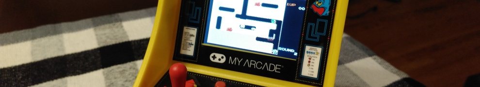
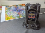
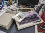
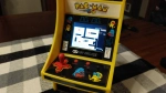
Miniature arcade machines were all the rage this year. A couple manufacturers offer different sizes, from 4″ tall, to 6″ and 10″ toys. I was given the ‘My
Arcade’ Pac-Man 6″ cabinet for Xmas, and I deserve credit for waiting a whole three days before breaking it open to look inside. 🙂
Regardless of whether you pick up the 4″ Tiny Arcade or the 6″ My Arcade version of your favorite game, chances are there are more games locked inside. To reduce manufacturing costs, groups of these games share a common circuit board and chip that contains 4-6 games, with only one of the games ‘unlocked’ for a particular toy. With a bit of modification, you can unlock the other games.
For example, the My Arcade 6″ Pac-Man I was given contained a total of 6 games:
- Pac-Man
- Galaga
- Mappy
- Galaxian
- Dig-Dug
- Rolling Thunder
As far as I can tell, Rolling Thunder isn’t even released as it’s own cabinet yet. The others can be found for $20-$30 at different stores. So, by unlocking them in my Pac-Man cabinet, I saved $125. I probably spent more than that in terms of time devoted to the mod, but that’s largely my own fault. More on that later.
Choose Wisely!
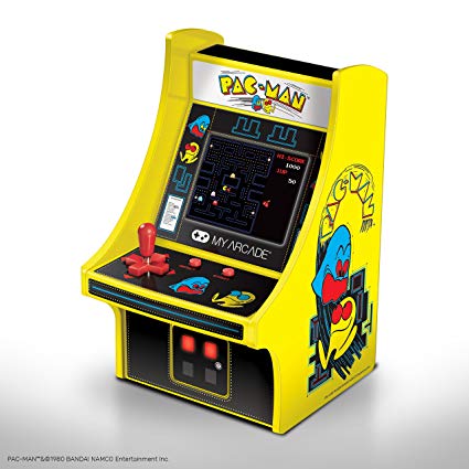
The Pac-Man I modded was a gift, but had I picked a cabinet to modify it would have been a different model. The 6″ Pac-Man from My Arcade contains no buttons, since Pac-Man does not require anything other than the directional controls. In order to make use of the unlocked games, which all require some kind of jump or fire input, buttons will be need to be added to the cabinet. If you are looking to mod one of these toys, save yourself the trouble and pick one that already has buttons.
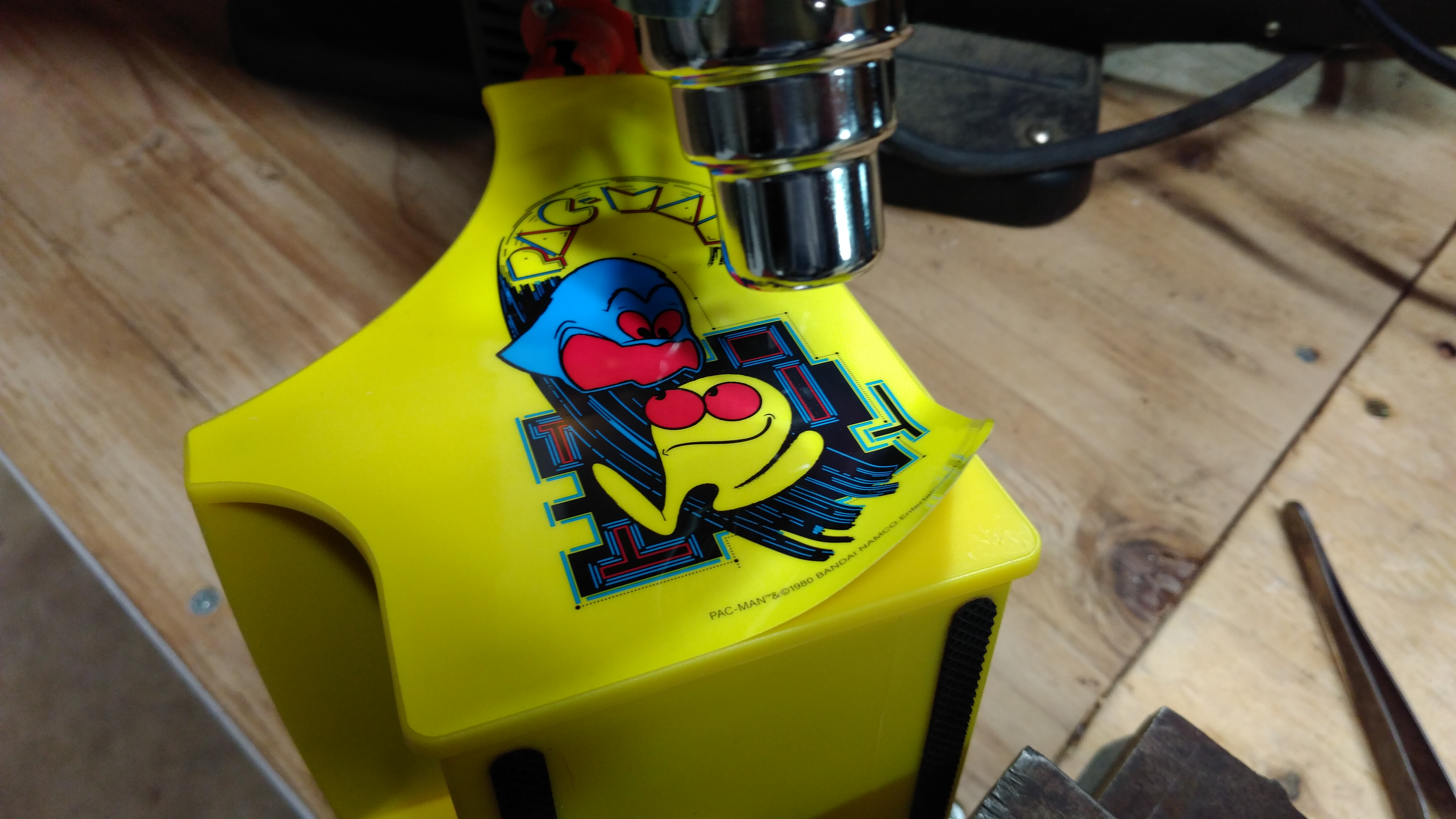
Stickers Can’t Stop us!
The first step is opening the cabinet is to remove some of the artwork stickers from the outside. Screws are hidden under the side artwork, and the top sticker crosses a seam that will need to be separated. Using a heat gun or hair dryer. Soften the glue and peel back these stickers. They are fairly thick and easy to remove once you get a corner up. Keep them somewhere safe for reassembly.
*2019 UPDATE* When I posted this article on the ‘My Arcade/Dream Gear Minis Fan Club‘ page on Facebook, someone replied that they were able to open their cabinet without removing the side art. On mine, the side panels had little wood screws under the stickers, and one poked through far enough to hold the back of the cabinet in place even after the 4 back screws were removed. Maybe I was just unlucky. Check yours first by removing the screws on the back of the cabinet before removing the side art. You might be able to skip this step.
With the side and top stickers removed, the screws can now be removed and the cabinet opened.
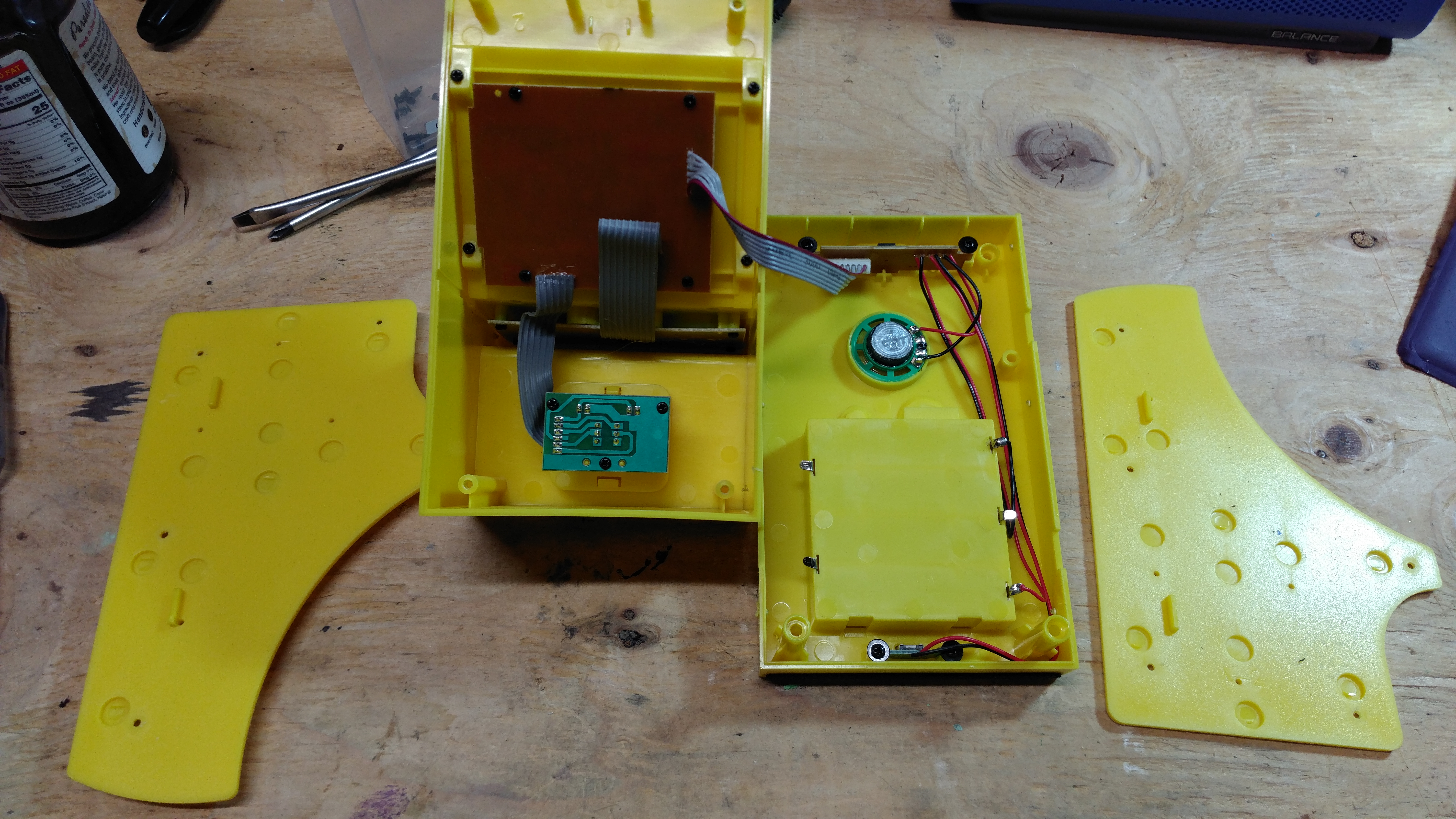
For cabinets with buttons already installed, these are all the stickers you’ll need to remove. If you are adding buttons to the front panel, you’ll also need to remove the front screen bezel sticker and plastic guard in order to remove the screen frame and slide out the control board.
Three bits, but only six games
Remove the main circuit board from the front of the cabinet and have a look. Under the padding, you’ll find three pairs of jumpers labeled IOB1, IOB2 and IOB3. These jumpers determine which game is unlocked in a particular cabinet. In this case, IOB1 is connected to enable Pac-Man. Through experimentation, I found that IOB3 unlocks Galaga and IOB2 unlocks Mappy and no connections unlock Rolling Thunder. But that’s not all. Some combinations also unlock games. IOB1 + IOB3 is Galaxian and IOB1 + IOB2 is Dig Dug. Sadly, although there are eight possible combinations, I was only able to find six that resulted in unlocking a game. All other combinations just launch Rolling Thunder, which must be the default game on the chip.
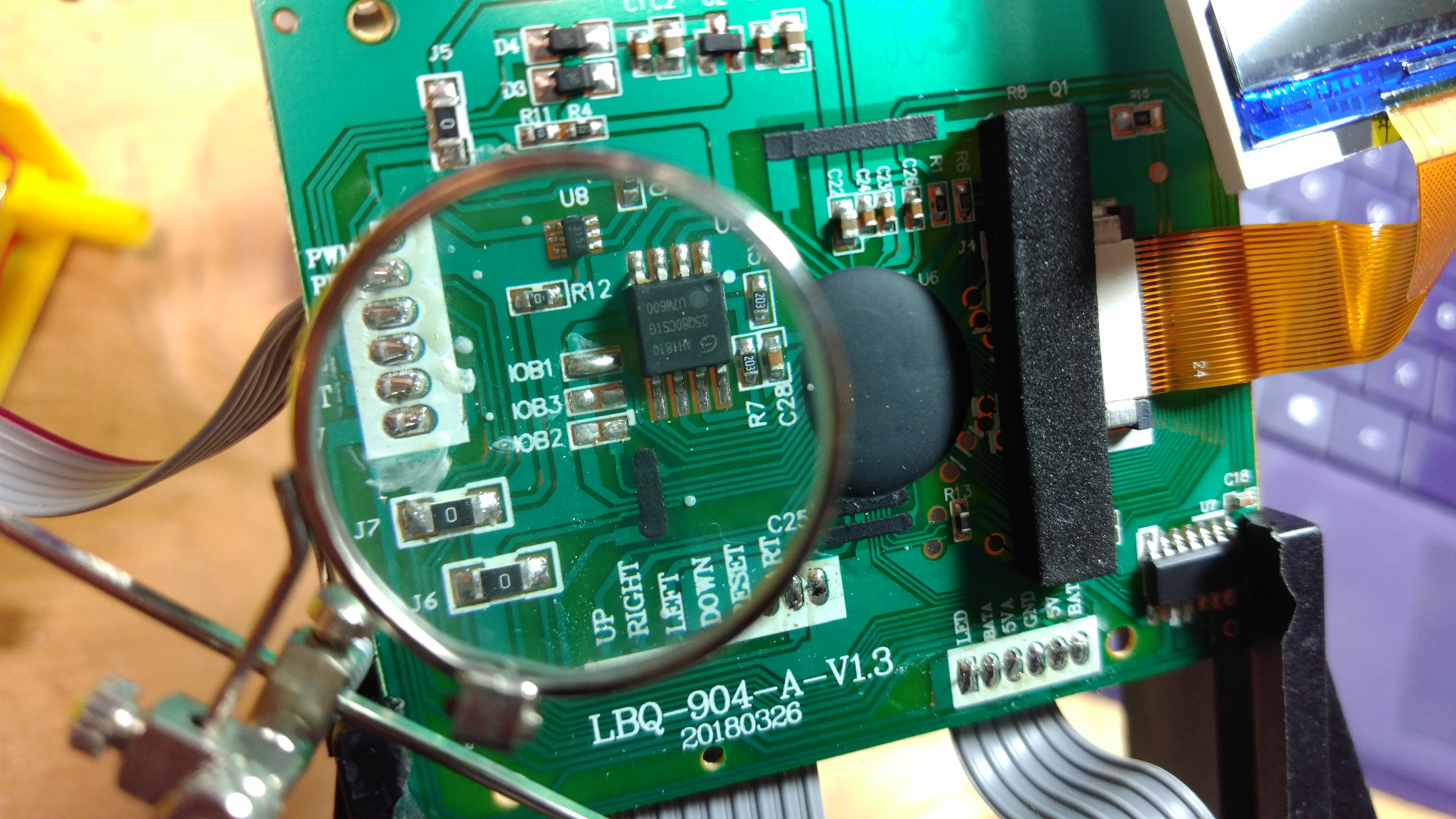
Since we need to independently set all three jumpers, I chose to remove the existing IOB1 solder joint and wire each pair of jumper pads to a switch. By setting the appropriate switches, I can then control which game boots when the power switch is turned on. Note that all three left pads are on a common trace. You only need to solder one wire to these pads and chain it to all three switches.
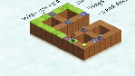
Here’s a drawing to help clarify. A switch is added across each jumper pad pair so they can be toggled by the user to pick the game before turning the system on.
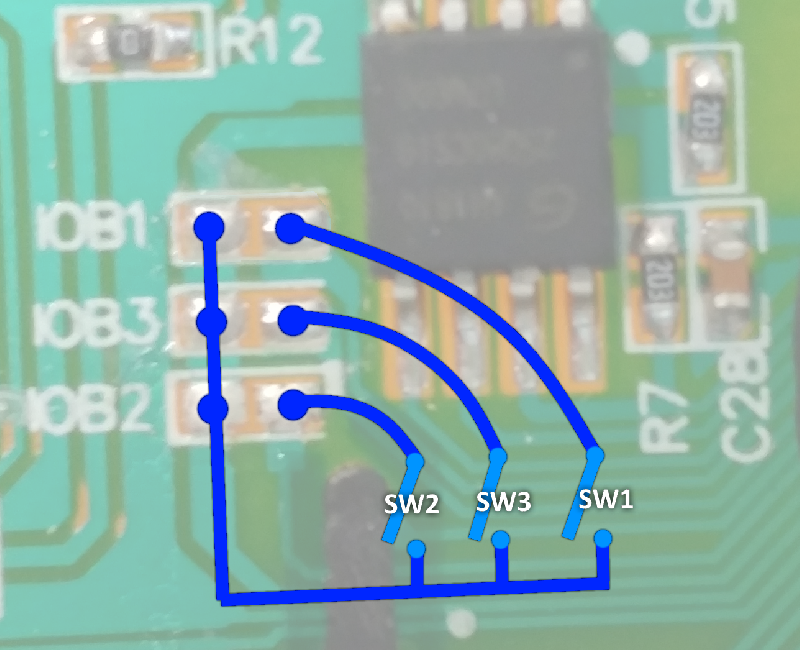
If no switches are closed, the system boots to Rolling Thunder
If only SW1 is closed, it boots to Pac-Man.
If only SW2 is closed, it boots to Mappy.
If only SW3 is closed, it boots to Galaga.
If only SW1 and SW2 are closed, it boots to Dig Dug.
If only SW1 and SW3 are closed, it boots to Galaxian.
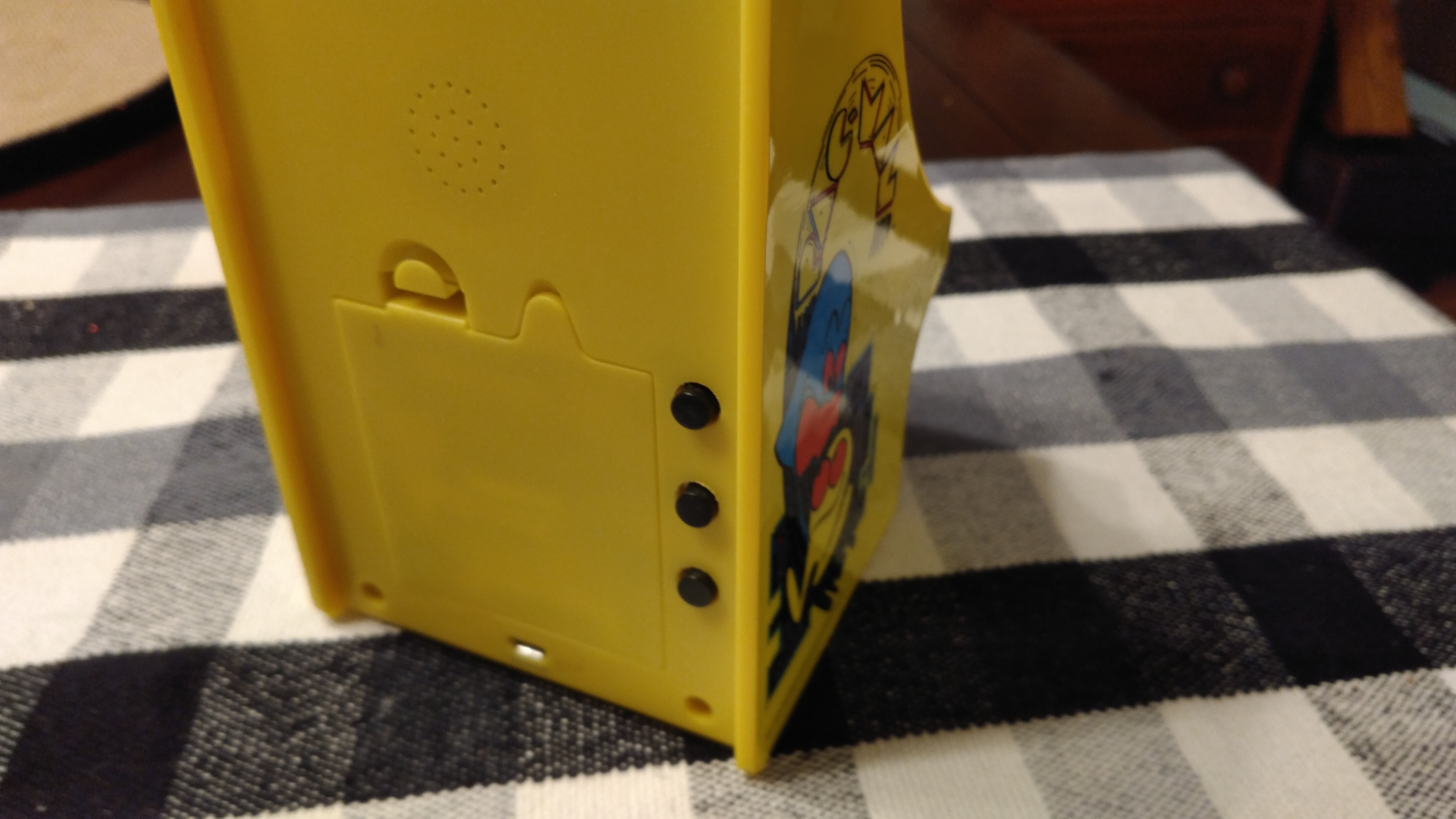
All I had available were some old Radio Shack push buttons, so I drilled three holes through the back of the cabinet and wired each to one of the jumper pads. By holding the proper combination of buttons when powering the unit on, I can now select one of the six games to play.
Use Caution! (and glue)
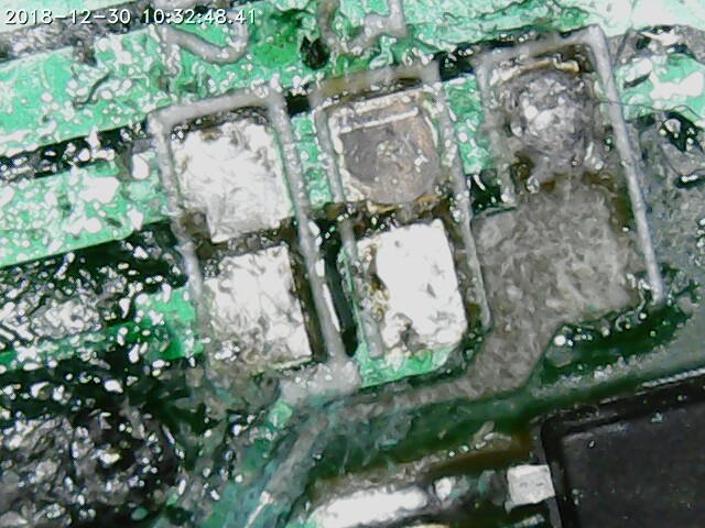
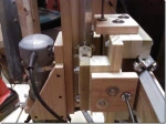
These circuit boards contain very thin traces. Try not to repeat the mistakes I made. If you solder a wire to one of the IOB pads, any slight tug on that wire will pull the pad and most of the trace it’s connected to right off the board. I did this more than once, and repairing circuit board traces can be a nightmare. In the microscope image below, you can see how the lower-right pad has been removed and also pulled a good chunk of copper trace with it. After taking this image, I did this two more times. *sigh*
In the end, I spent an entire afternoon repairing the board of a $25 toy. My advice is to make sure you hot-glue or tape your wires down as soon as possible to avoid pulling them off the board, and practice your soldering skills to make sure you can connect items quickly without burning a trace. You’ll also need a sharp soldering iron point to work on these small areas.
Control Issues
Since the source for this mod was a Pac-Man cabinet with no game buttons, some will need to be added. Otherwise, we can’t play any of the unlocked games. All the unlocked games require one button except Rolling Thunder which needs two. Luckily, the control board is also shared between all the cabinets. The button pads are present, but simply unpopulated on the Pac-Man machine.
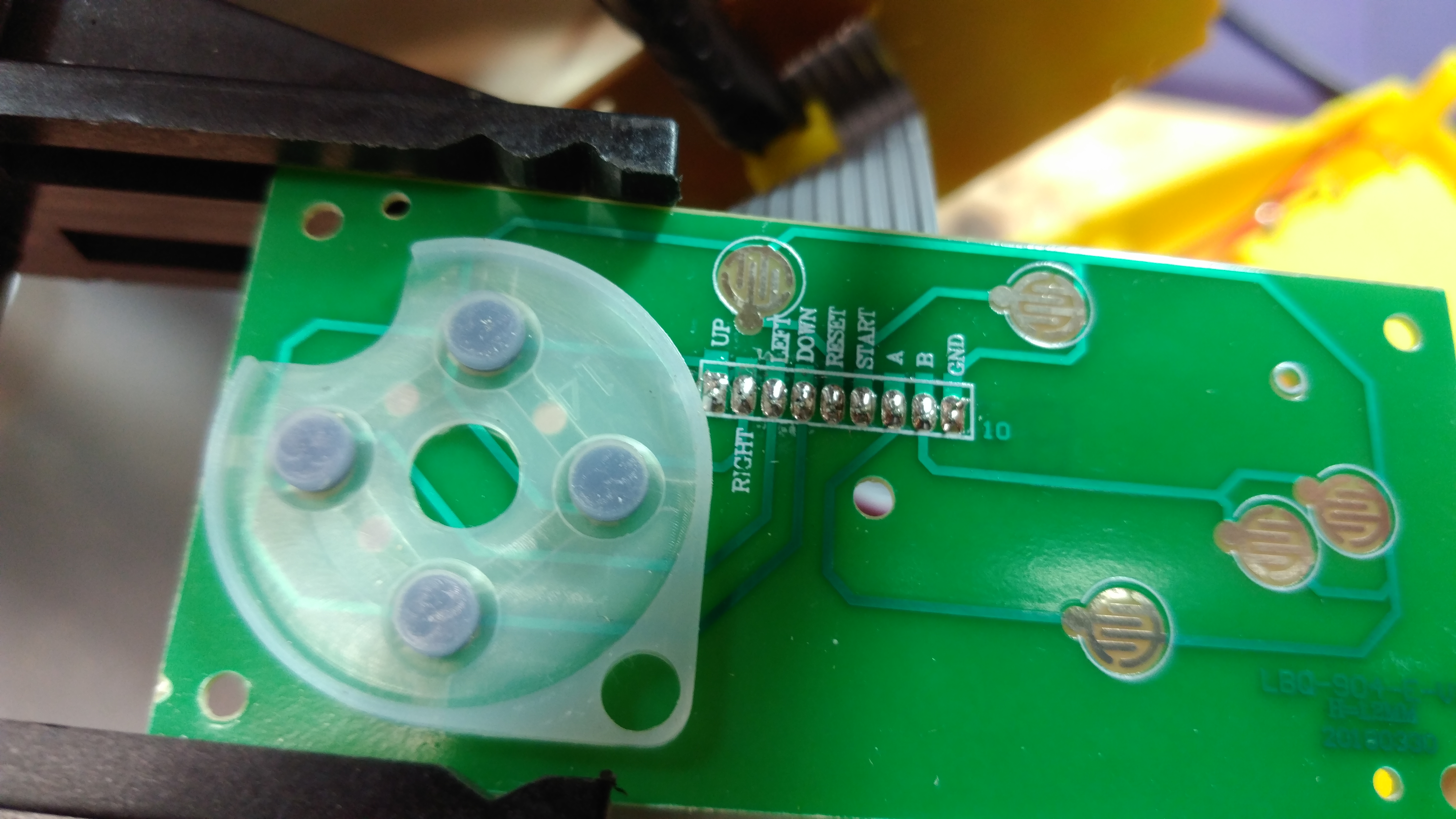
For my mod, I chose to just wire two more small buttons to the A and B pads, connecting each to GND when pressed. The switches are small, since I wanted to minimize the size of the holes I need to make in the control board to preserve the artwork. I also shifted them up so they’d work well with the Pac-Man art. Small felt bumpers were hot glued under each switch to raise them up to the height needed.
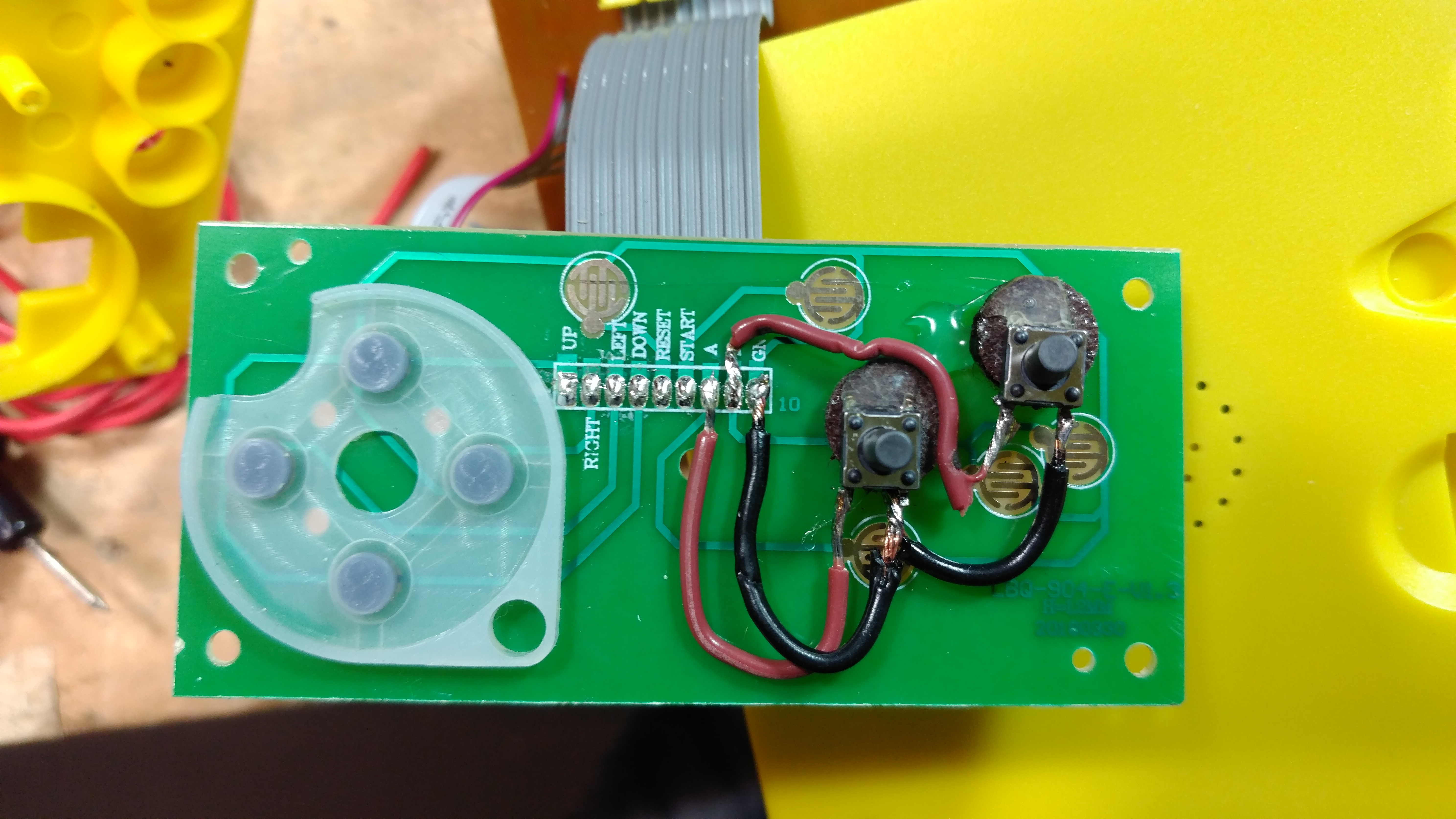
The end result works, and the small black buttons are somewhat camouflaged by the dark background of the Pac-Man art.

Conclusion
With a bit of effort, and a source cabinet with existing gameplay buttons, this mod can be done in an evening. With my poor luck damaging the board and needing to add additional gameplay controls, the mod took two days. Still, it’s a fun modification that results in 5 more games to play. Highly recommended.
Happy Modding!


That’s awesome! Would you happen to be willing to do this to my galaga cab? A commission?
Thanks for the offer, but I’m not taking on commissions right now. Plus, I really butchered the circuit board in my own unit, so I’m not the right person to try and do this as a service!
Ok no problem! I LOVE rolling thunder but I don’t know how to do this stuff sadly..,
might it be possible to utilize the 8 position joystick position as the switch, as was done for the Tiny Arcade?
Yes. I think it would but I have not tried it. If I get a second one, that’s probably what I’ll do.
Hi! i did the mood thanks for the article, really helpful. but i used and old ps3 controler, i removed the X button and the Square and use them on the board butons and it works great! i driled the holes and tested the buttons, and now it feels almost like a Nes controler!
if anyone wold like to use my method with an old ps2..3 controller, you will need to check the size of the buttons.
the x , triangle , square and 0 will work great
when you said you set a switch to each jumper pad . how would you do that and can i get a picture for clerity
I tried to mod my father’s Pac-Man to do this. Have the same board (version number) they cut the traces to the pads. So tapped in to the traces on the board going to the main processor and this doesn’t seem to work on newer ones. when I open all the pad/switches it only ever boots pac-man.
Crud. I suppose it’s been long enough that they might have changed the design to help prevent the mod from working. Next time I see a new one on sale I’ll pick it up and see if I can get the mod to work.
I’ll get one this week and check if the models we have available here in the Middle East can be hacked
See if you can get a voltage reading on the connections. Check if it is pulsed or solid… If it is pulsed, you may be able to use a tiny capacitor or resistor to alter the signal. If it is solid, just a resistor to try to reduce the voltage by half. That may be read as more “settings”, as opposed to just being ON and OFF from a switch. The connections could be High/ON, Low/HALVED, Null/OFF. R7 and C28 also look like they may have a role in the switches too, if that trace goes directly under the chip. If the connections are just ON/OFF, then it may be R7 and C28 controlling the “level” of the connections closed-states. (I’d test another resistor on R7, to halve the resistance, and possibly try shorting it, to see if it does anything. Unless it is just holding the connections to a specific input voltage to make it “safe” for the exposed chip or the “epoxy-dot” chip.) I can’t think of any other reason it would link the two chips together, through those switches, on a common.