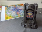
A short time ago I built a miniature version of the 1981 electronic board game Dark Tower as a gift. This project combined 3D printing with some electronics and game programming. It was a ton of fun to design and build.
I decided to record the process and put it up on YouTube. This was a promise I made myself for 2022 to get more active in the Maker community. This is one of the first projects I recorded. As you might expect, most of that recording was garbage. Just me rambling while working on the project with a camera in one hand. Thankfully, through the wonders of editing, I was able to distill it down into (I think) a couple fun videos. Check them out over on my YouTube channel.
I’ll take a moment here to beg for a click on those Like and Subscribe buttons. Seriously. It means a lot to have these efforts validated with a thumbs-up. Costs you nothing and lets me know folks are out there. Constructive feedback is also appreciated so can improve the quality of the next video project. Want to see more details on coding? The 3D design process? Assembly? Help guide the next video project by letting me know what aspects you want to see more of.
Wanna build one? Links to the source code, 3D models and parts list can be found in the second video description.
Part 1: Intro to the game and the plan to rebuild it.
Part 2: Doing the thing I said I’d do in Part 1. 🙂
I have a few video projects coming up in the new year. We’re getting an old C64 back up and running, remaking a classic 1980’s electronic board game with Arduino, 3D printing some robot gears and trying our hand at crafting a mini pinball table. It’s gonna be a full 2022!
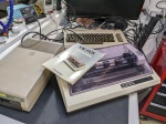
To kick things off a little early, I’m launching the first series before 2021 ends. This is about finding my own 1984 computer in my parent’s attic and the process of getting it running again. Check it out over on YouTube, and do the “like“, “subscribe“, “comment” thing while you are at it. 🙂
UPDATE: Parts 2, 3 and 4 of this epic struggle have also been published. Check out the whole series. We cover video issues, broken audio. discolored plastic and busted keys. There was no part of this C64 that wasn’t broken. *sigh*
Miniature arcade machines were all the rage this year. A couple manufacturers offer different sizes, from 4″ tall, to 6″ and 10″ toys. I was given the ‘My Arcade’ Pac-Man 6″ cabinet for Xmas, and I deserve credit for waiting a whole three days before breaking it open to look inside. 🙂
Regardless of whether you pick up the 4″ Tiny Arcade or the 6″ My Arcade version of your favorite game, chances are there are more games locked inside. To reduce manufacturing costs, groups of these games share a common circuit board and chip that contains 4-6 games, with only one of the games ‘unlocked’ for a particular toy. With a bit of modification, you can unlock the other games.
For example, the My Arcade 6″ Pac-Man I was given contained a total of 6 games:
Pac-Man
Galaga
Mappy
Galaxian
Dig-Dug
Rolling Thunder
As far as I can tell, Rolling Thunder isn’t even released as it’s own cabinet yet. The others can be found for $20-$30 at different stores. So, by unlocking them in my Pac-Man cabinet, I saved $125. I probably spent more than that in terms of time devoted to the mod, but that’s largely my own fault. More on that later.
Choose Wisely!
The Pac-Man I modded was a gift, but had I picked a cabinet to modify it would have been a different model. The 6″ Pac-Man from My Arcade contains no buttons, since Pac-Man does not require anything other than the directional controls. In order to make use of the unlocked games, which all require some kind of jump or fire input, buttons will be need to be added to the cabinet. If you are looking to mod one of these toys, save yourself the trouble and pick one that already has buttons.
Stickers Can’t Stop us!
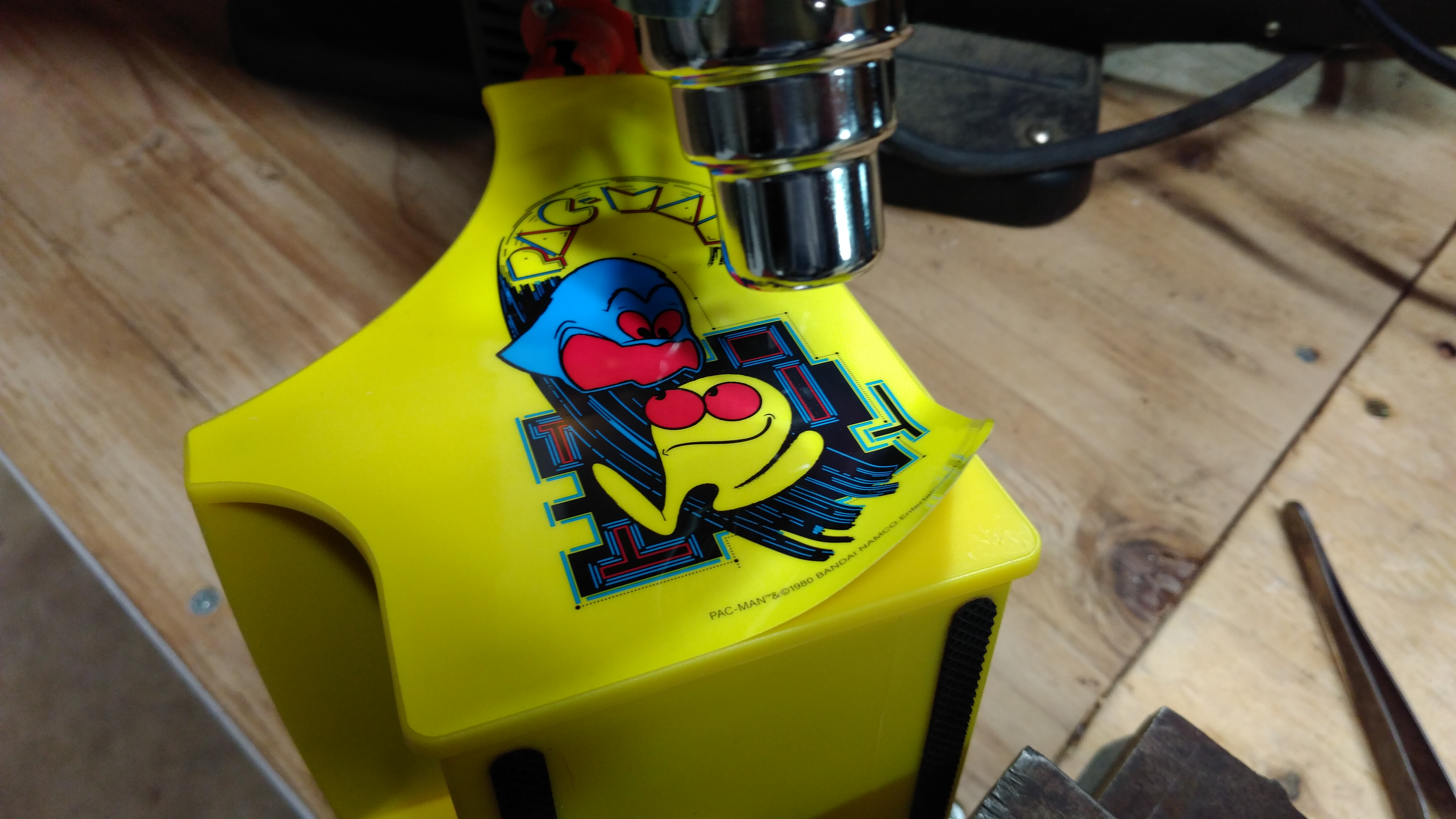
The first step is opening the cabinet is to remove some of the artwork stickers from the outside. Screws are hidden under the side artwork, and the top sticker crosses a seam that will need to be separated. Using a heat gun or hair dryer. Soften the glue and peel back these stickers. They are fairly thick and easy to remove once you get a corner up. Keep them somewhere safe for reassembly.
*2019 UPDATE* When I posted this article on the ‘My Arcade/Dream Gear Minis Fan Club‘ page on Facebook, someone replied that they were able to open their cabinet without removing the side art. On mine, the side panels had little wood screws under the stickers, and one poked through far enough to hold the back of the cabinet in place even after the 4 back screws were removed. Maybe I was just unlucky. Check yours first by removing the screws on the back of the cabinet before removing the side art. You might be able to skip this step.
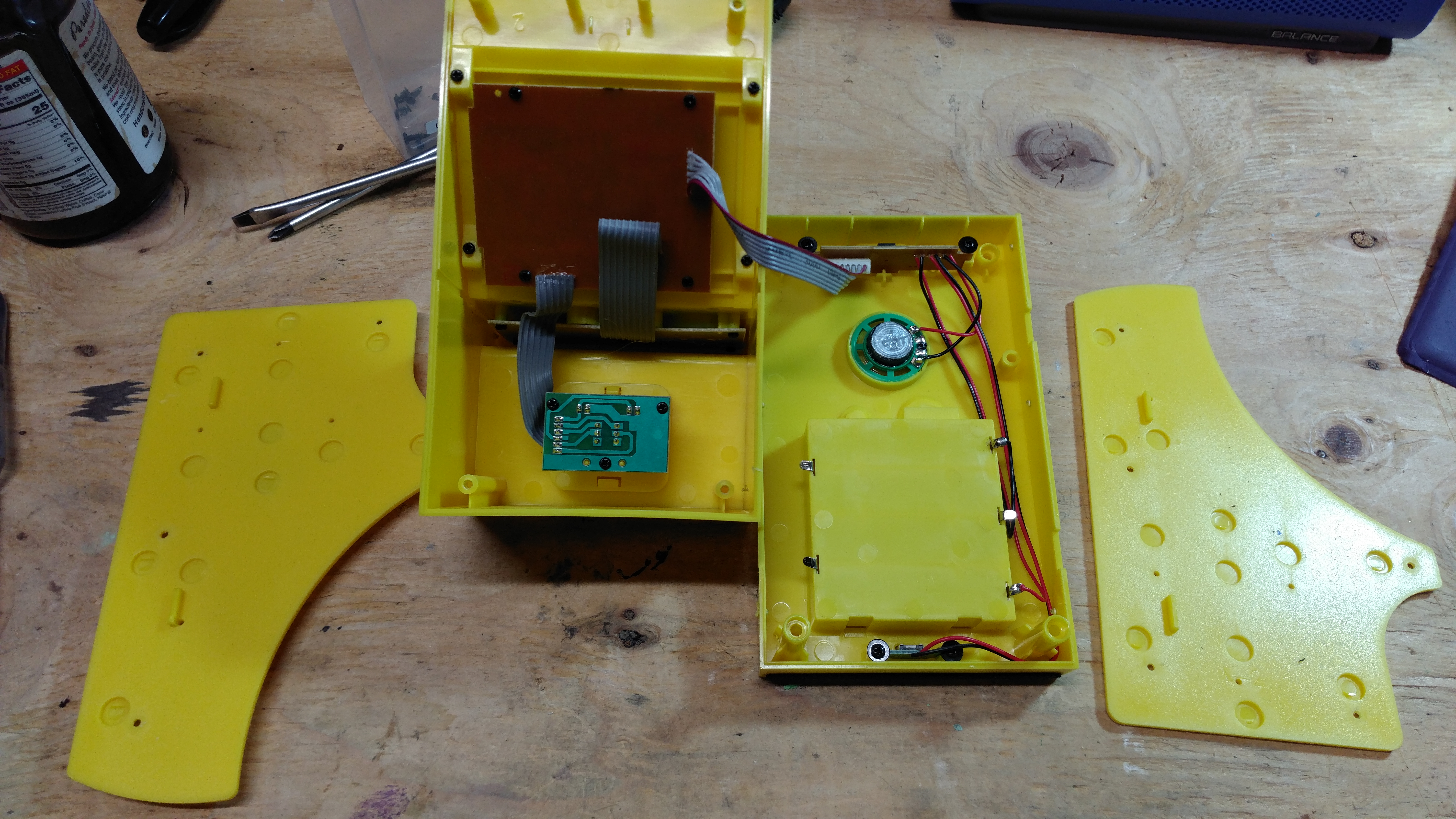
With the side and top stickers removed, the screws can now be removed and the cabinet opened.
For cabinets with buttons already installed, these are all the stickers you’ll need to remove. If you are adding buttons to the front panel, you’ll also need to remove the front screen bezel sticker and plastic guard in order to remove the screen frame and slide out the control board.
Three bits, but only six games
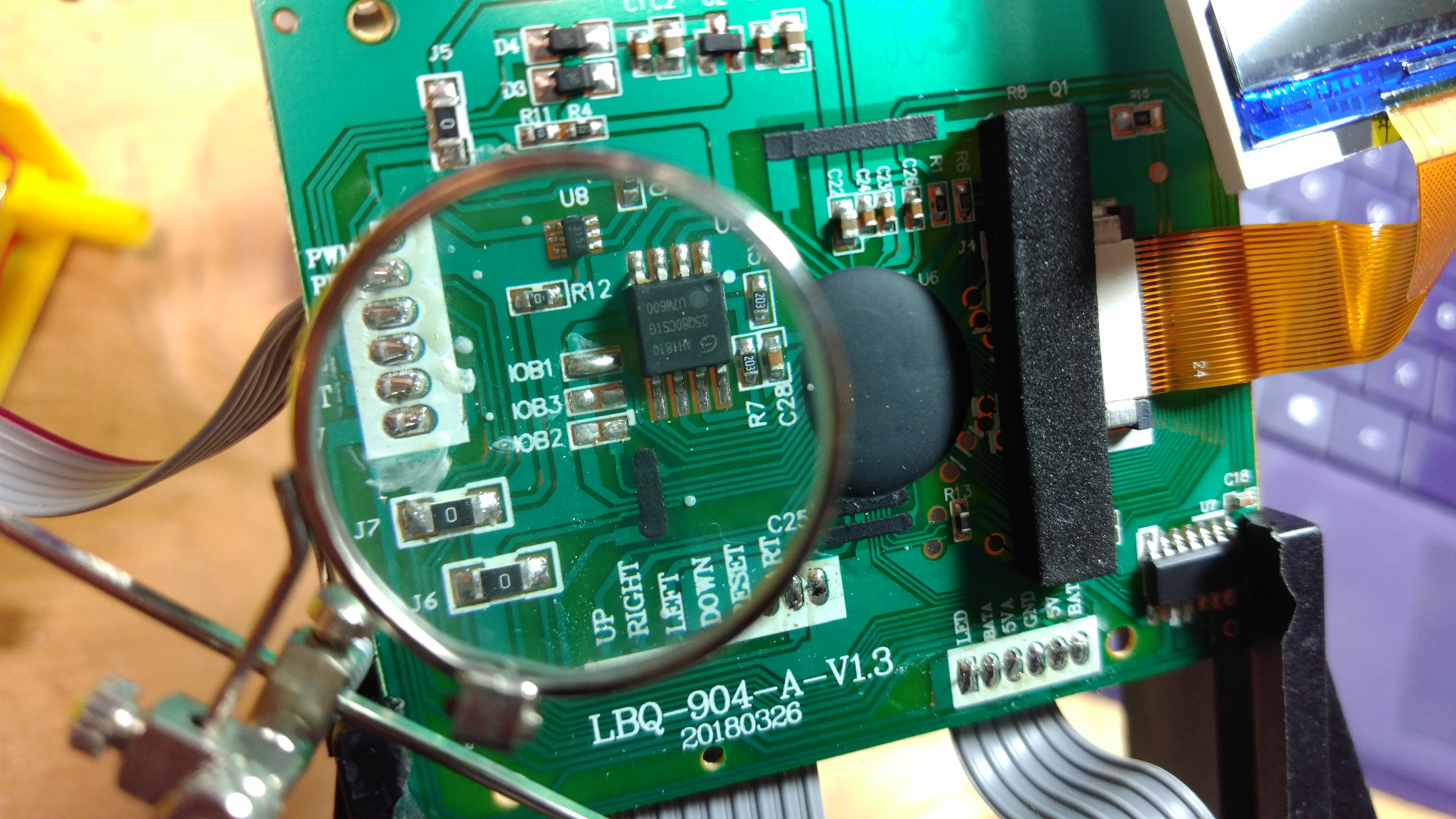
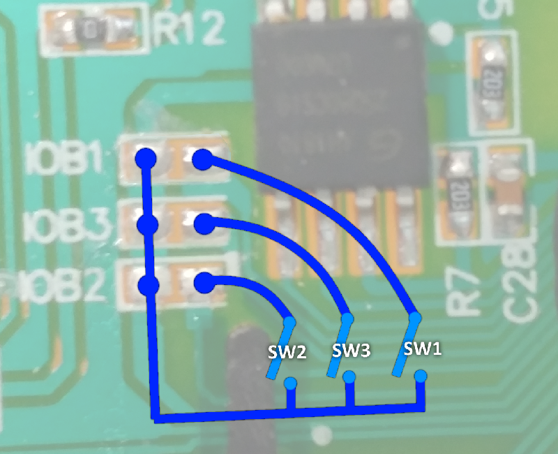
Remove the main circuit board from the front of the cabinet and have a look. Under the padding, you’ll find three pairs of jumpers labeled IOB1, IOB2 and IOB3. These jumpers determine which game is unlocked in a particular cabinet. In this case, IOB1 is connected to enable Pac-Man. Through experimentation, I found that IOB3 unlocks Galaga and IOB2 unlocks Mappy and no connections unlock Rolling Thunder. But that’s not all. Some combinations also unlock games. IOB1 + IOB3 is Galaxian and IOB1 + IOB2 is Dig Dug. Sadly, although there are eight possible combinations, I was only able to find six that resulted in unlocking a game. All other combinations just launch Rolling Thunder, which must be the default game on the chip.
Since we need to independently set all three jumpers, I chose to remove the existing IOB1 solder joint and wire each pair of jumper pads to a switch. By setting the appropriate switches, I can then control which game boots when the power switch is turned on. Note that all three left pads are on a common trace. You only need to solder one wire to these pads and chain it to all three switches.
Here’s a drawing to help clarify. A switch is added across each jumper pad pair so they can be toggled by the user to pick the game before turning the system on.
If no switches are closed, the system boots to Rolling Thunder If only SW1 is closed, it boots to Pac-Man. If only SW2 is closed, it boots to Mappy. If only SW3 is closed, it boots to Galaga. If only SW1 and SW2 are closed, it boots to Dig Dug. If only SW1 and SW3 are closed, it boots to Galaxian.
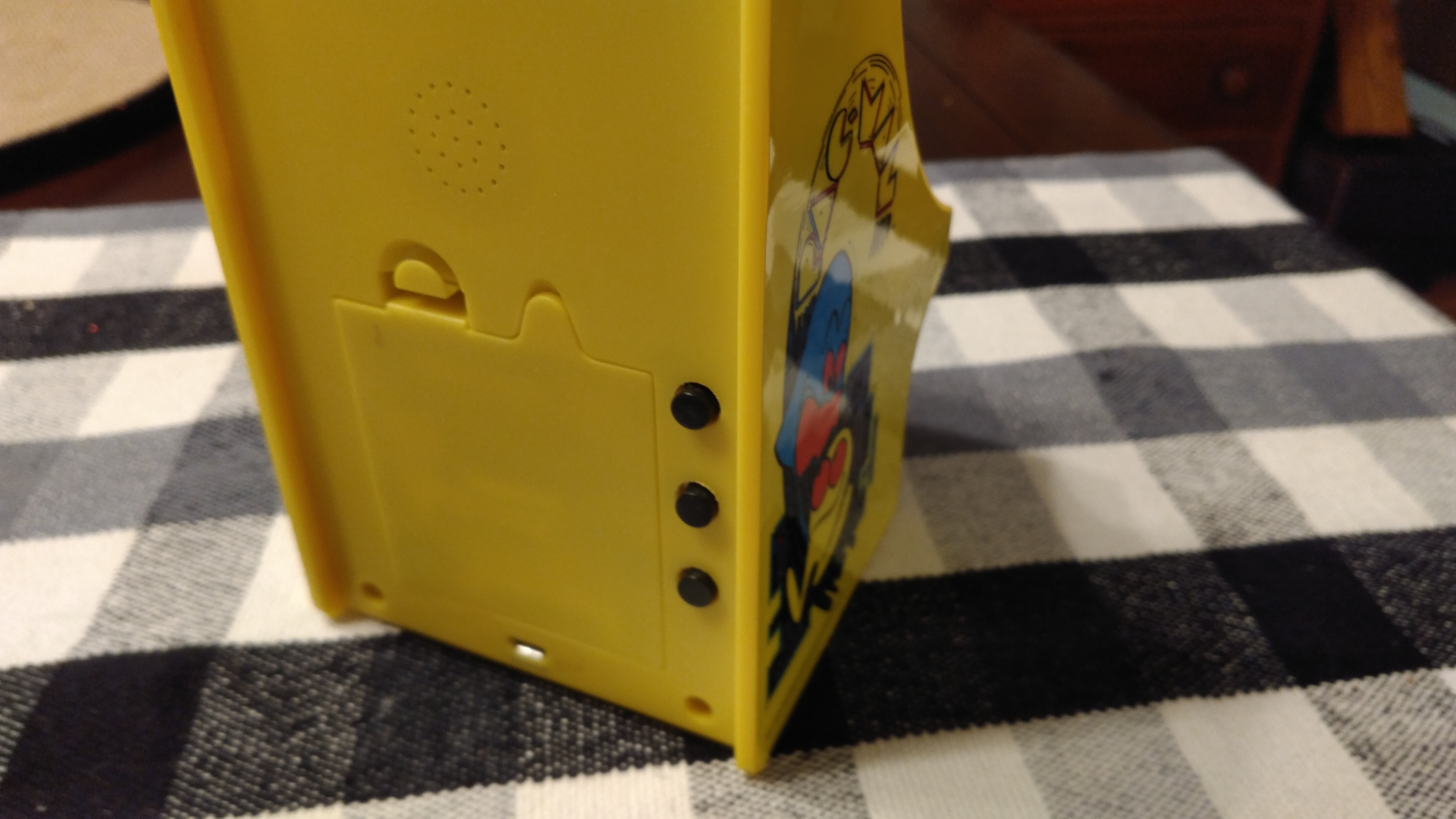
All I had available were some old Radio Shack push buttons, so I drilled three holes through the back of the cabinet and wired each to one of the jumper pads. By holding the proper combination of buttons when powering the unit on, I can now select one of the six games to play.
Use Caution! (and glue)
These circuit boards contain very thin traces. Try not to repeat the mistakes I made. If you solder a wire to one of the IOB pads, any slight tug on that wire will pull the pad and most of the trace it’s connected to right off the board. I did this more than once, and repairing circuit board traces can be a nightmare. In the microscope image below, you can see how the lower-right pad has been removed and also pulled a good chunk of copper trace with it. After taking this image, I did this two more times. *sigh*
In the end, I spent an entire afternoon repairing the board of a $25 toy. My advice is to make sure you hot-glue or tape your wires down as soon as possible to avoid pulling them off the board, and practice your soldering skills to make sure you can connect items quickly without burning a trace. You’ll also need a sharp soldering iron point to work on these small areas.
Control Issues
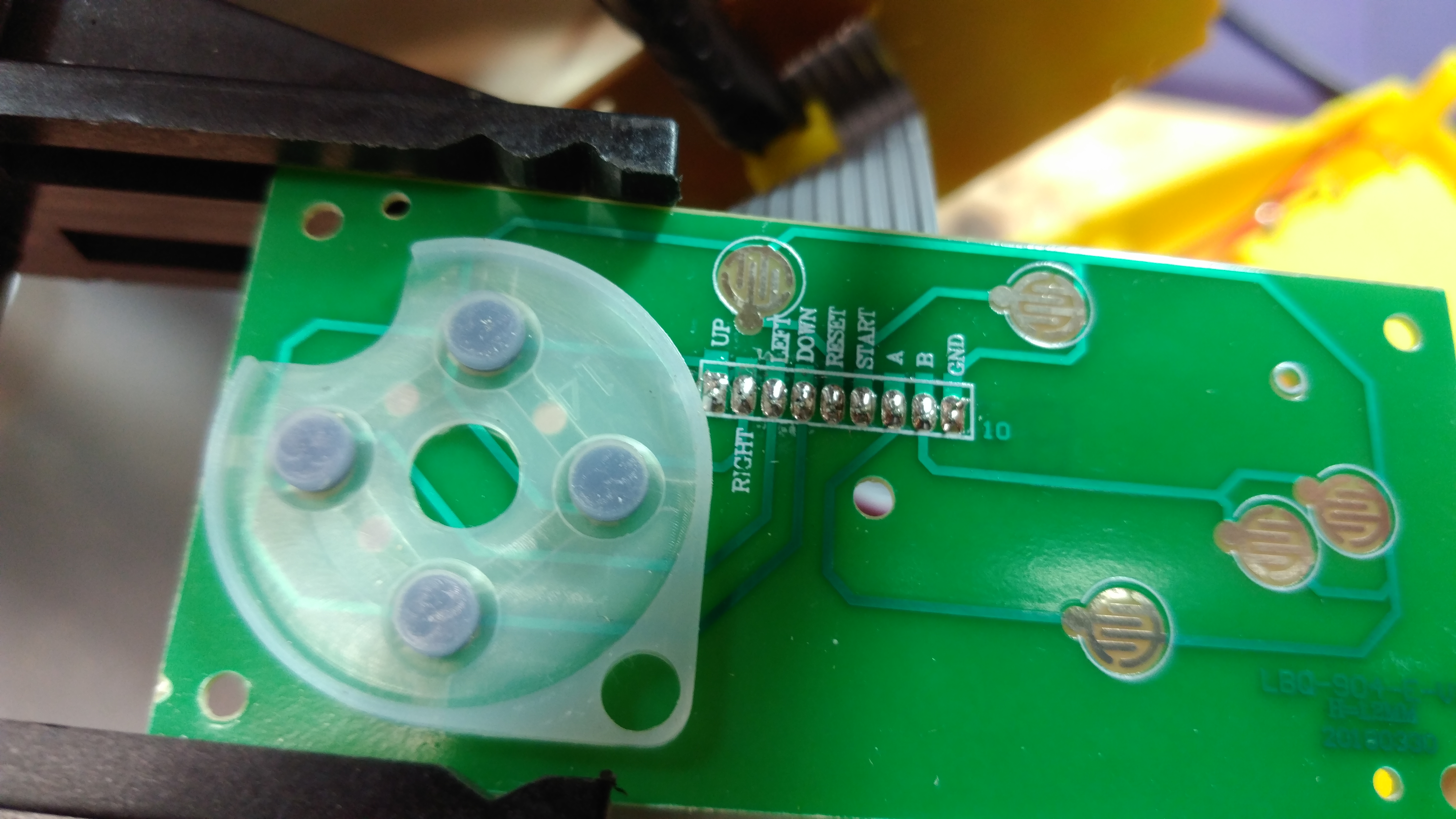
Since the source for this mod was a Pac-Man cabinet with no game buttons, some will need to be added. Otherwise, we can’t play any of the unlocked games. All the unlocked games require one button except Rolling Thunder which needs two. Luckily, the control board is also shared between all the cabinets. The button pads are present, but simply unpopulated on the Pac-Man machine.
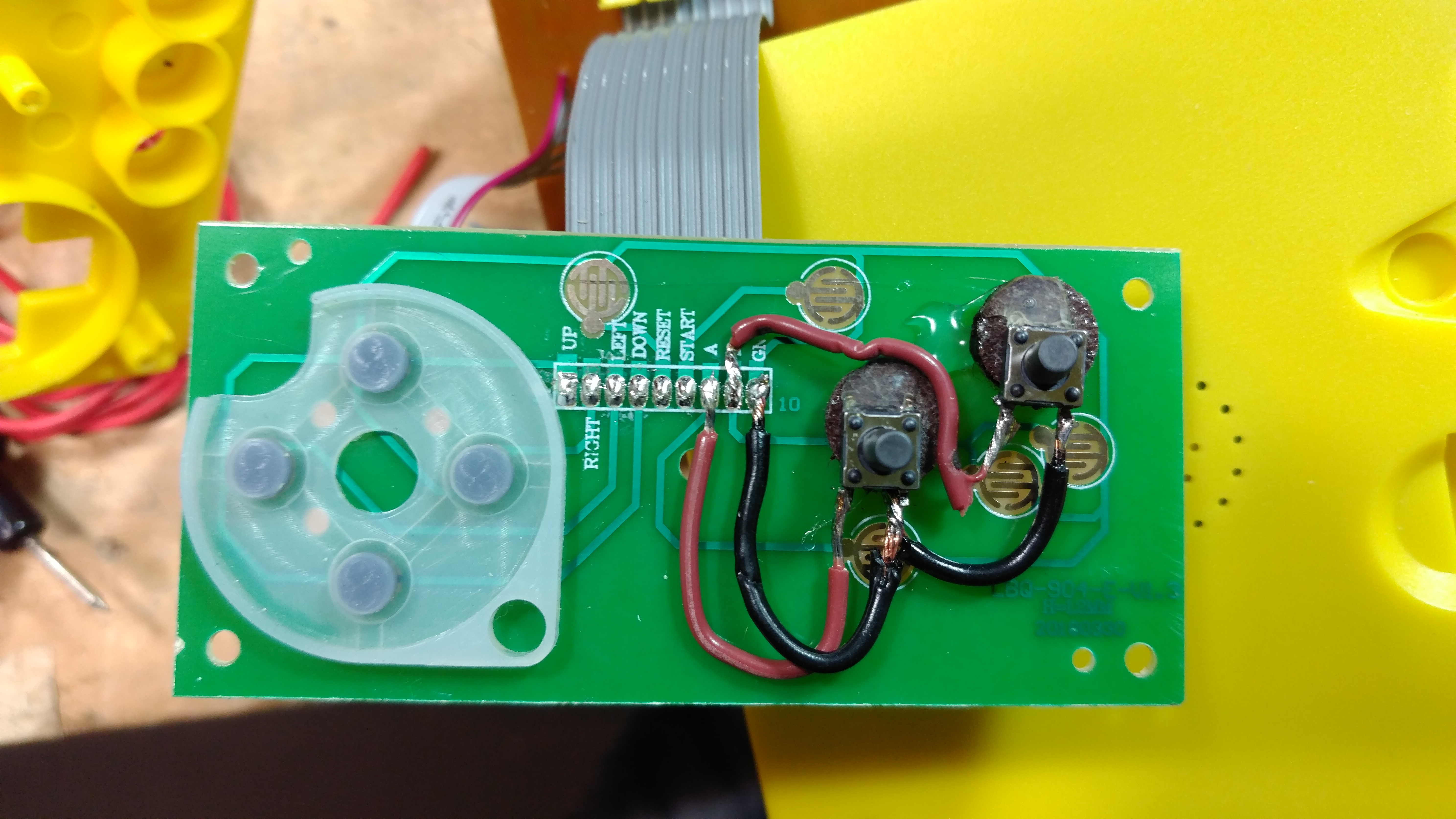
For my mod, I chose to just wire two more small buttons to the A and B pads, connecting each to GND when pressed. The switches are small, since I wanted to minimize the size of the holes I need to make in the control board to preserve the artwork. I also shifted them up so they’d work well with the Pac-Man art. Small felt bumpers were hot glued under each switch to raise them up to the height needed.
The end result works, and the small black buttons are somewhat camouflaged by the dark background of the Pac-Man art.
Conclusion
With a bit of effort, and a source cabinet with existing gameplay buttons, this mod can be done in an evening. With my poor luck damaging the board and needing to add additional gameplay controls, the mod took two days. Still, it’s a fun modification that results in 5 more games to play. Highly recommended.
As my indie game, Skyling: Garden Defense, is getting further along, I decided to setup a small company to house that effort. Mighty Studios, LLC has now been formed, and I’ll be moving most progress updates about the game under that banner. Check out www.mightystudios.com for all the latest info on the game. Links to the facebook page, twitter feed, and all sorts of other ways to stay informed on the game can be found there. Check it out and share your thoughts on the game. I look forward to hearing your feedback!
I’ve done a bit more tuning on the CNC machine, and it’s running better than ever. First, I discovered a bit of useful data regarding stepper motor torque and micro-stepping. micro steps allow you to get greater precision from your stepper. Steppers are fed pulses from the controller board, where each pulse moves the motor a fixed increment. In my case, the steppers I use take 200 steps per revolution. If you needed greater precision than that, you can use micro-steps to send pulses that move the motor a fraction of a step at a time. For example, if I used 8x microsteps on my motors that are normally 200 pulses per revolution, they would jump to 1600 pulses per revolution. The micro steps can get you extra precision, but as this data shows the cost in torque can be quite high. I hadn’t realized that when I first setup my control board.
To get the most out of my little SparkFun steppers, I need all the torque I can get. The EasyDrivers are set by default to use 8x micro steps, but that can be disabled by jumping a couple pins to ground (as explained on the EasyDriver site). I don’t need the extra precision of micro-steps from my rig, since the motors turn 14-20 threaded rod to drive the CNC along an axis. 14-20 rod is 20 revolutions per inch, or 0.787 revolutions per mm. So each pulse is only moving the rig 1/157th of a millimeter. That’s enough precision for me! So, I did a bit of soldering and set each of the three motor controllers to use full resolution steps – and I’m now operating at 100% torque. Well, as much as these little motors can push anyway.
Next, I upgraded GRBL to the latest ‘beta’ version to take advantage of the max speed settings they added. These little SparkFun steppers stall at speeds over ~225mm/min so I need to keep them capped at about 190mm/min. With the current stable version of GRBL (0.8c), I was encountering issues where the motion planner would occasionally use higher speeds than those present in the gcode being processed. If I was cutting something using gcode settings of 200mm/min, GRBL would occasionally create runs that topped over 300mm/min and stall the motors. This usually occurred on axis-aligned paths. Crazy, and a pain in the ass to debug! But, after experimenting with the beta version of 0.9a, and capping it’s max speed, the same gcode is now working as expected. Go figure!
These little steppers still need a lot of wind up time before getting to top speed. In the GRBL settings, I have to keep the acceleration limits very low to maintain accuracy. When I bring them higher, the cutting path loses all accuracy and I end up just cutting gibberish. If you are working with the same SparkFun stepper motors and EasyDriver boards, here’s the GRBL settings I arrived at today after a bunch of tuning. Keep in mind this is also for 14-20 threaded rod, so your settings may differ.
I hope that saves you some time. Killed my whole afternoon!
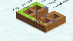
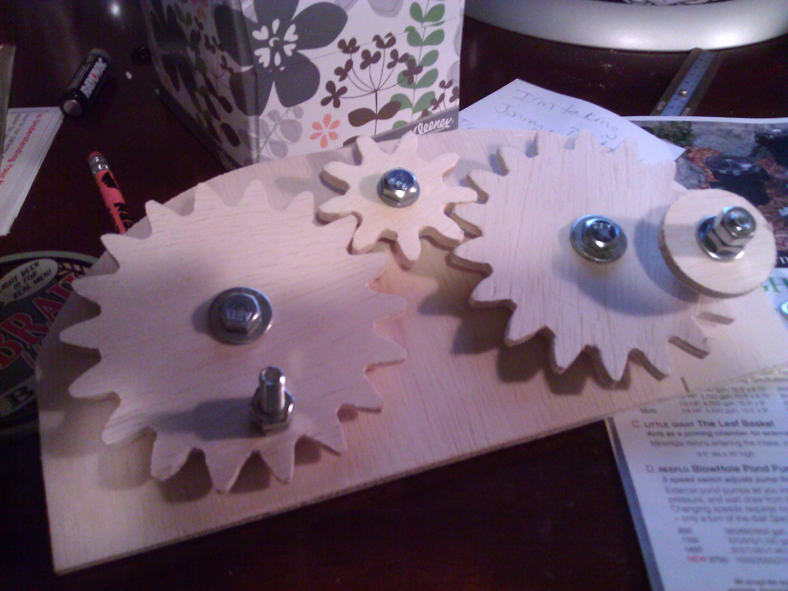
But they payoff was worth it. I cut some gears out of 1/4″ birch as a precision test, and they turned out perfect. Here’s a shot of the gear drawing in SketchUp, and the CNC in action cutting out the gear assembly shown at the top of this post.
It turns smooth as silk. Very encouraging for some of the projects I have planned. 🙂
UPDATE 3/28/2013: I totally forgot to mention the speed gain achieved by removing microsteps. In the initial build, the axis travel was limited to 50mm per minute to maintain torque. With the new setup, I’m now running at 190mm per minute. Still slower than most CNCs of this size, but good enough for my homebrew work.
This is a follow up on the last post about the CNC machine I recently built (https://gsnook.wordpress.com/2012/12/15/cnc-machine-2012/). After a few weeks of putting the project on hold, I finally found time to make some improvements to the design.
The carriage on the overhead gantry had a bit too much flex on it, so I decided to stiffen it up. The new carriage runs a lot better, which will hopefully improve the accuracy of the machine. It’s still not as sturdy as it could be, but it’s much better than before.
To see the difference, have a look at the original carriage design:
This is a basic design where the carriage piece is built from two perpendicular C-shaped clamps. One clamp is gripping the Y axis rail, and the other is gripping the Z axis rail. The wood blocks holding the skate bearings have slots cut in them for the mounting bolts to pass through, making them adjustable. To set the tension, you squeeze the clamp on the rail using a second pipe clamp, then tighten the bolts to hold the tension.
I made this assembly more adjustable than it needs to be. In the picture above, you can see the extra spacers added for adjustment nuts to fine tune the position of the skate blocks. This air gap proved to be a bad flex point, so it needed to change. There is also no real adjustment needed to set the skate blocks into the proper position, so the design was really overkill.
You can also see that the threaded rod passes through fixed wood blocks, into which I had imbedded 1/4” thread couplers. These caged coupler nuts riding on the threaded rod is what pushes the carriage along the rails. After using the machine for a while, it was clear that having the threaded rod pass through these fixed blocks was a tuning nightmare. If the carriage was not plumb, these blocks would bend the threaded rod and make it harder for the motor to spin them. After all the thought I put into adjusting the skate blocks, not being able to adjust the push blocks was a big oversight.
Luckily, the new carriage design fixes both issues.
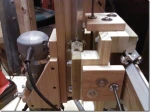
First, I stopped by my local Ace Hardware and found these awesome bits. These are 14-20 threaded stop nuts, which are essentially 1/4” nuts with a bulkhead flange. I also found rubber washers that matched. These replace the old coupling nuts that were causing me so much grief.
In the second picture, I’m showing the new push block these nuts are mounted onto. The rubber washer is sandwiched between the block and the nut, which is held in place with three set screws. The assembly is screwed in tight, but not so that it is completely squashing the rubber washer. This rubber gasket provides just enough wiggle room for the nut to ride along the threaded rod even if the carriage is slightly off plumb.
You can also see the two lag screws which are used to mount the block sitting in oversized holes. This is also for ease of assembly and adjustment. In the final assembly, the lag screws will have fender washers to clamp the block down. The Oversized holes let me adjust the position of the block until it’s just right, then lock it all down.
These last two pictures show the final build of the new carriage. Note that the old air gaps are gone making the carriage one solid piece. Each axis now also has a new push block on it’s threaded rod using the improved stop nut design.
The end result has much less flex, and no binding of the threaded rod.
A CNC Machine is something that you just have to have once you’ve seen one in action. It seems to hit that DIY tinkerer sweet spot in the brain that says “I must build this! I don’t know why, but I have to!” It’s a thing you build so you can build other things – including better CNC machines. How awesome is that?
Here’s an overview of the CNC machine I recently completed. Rather than post step-by-step as I built it, I decided to finish it first and then write a synopsis of what worked and what didn’t. Hopefully this will help out anyone starting out with their own designs.
First of all, I should state what my goals were for this design. I had some unique limitations based on the tools and skills I have, so I needed a design that worked for me. I also wanted a low-cost, flexible platform that could be used for a lot of different computer-controlled applications. Everything from CNC carving to 3D printing and even programmable camera controls for Toymation.
Materials
There are a ton of excellent, free CNC designs available on the web. However, most didn’t line up with the limited tools and woodworking skills I have. Most required cutting pieces out of thick 4’x8’ MDF panels to construct the parts. This was an issue for me since A) I don’t have a way to transport these panels home from the store, and B) I suck at cutting precise shapes out of panels with the tools I have.
Minor Rant: Ben Heck has a wonderful show on Element14 where he builds a ton of impressive gadgets. I was so excited to see he had an episode on building a CNC machine. Unfortunately, that episode should have been titled ‘How to build a DIY CNC machine using the large, industrial CNC machine you already own’. Cheater. Still, it’s recommended viewing so see how a basic machine works.
My limited options meant creating a design that used dimensional lumber and could be assembled with a simple chop saw, a drill press and a Dremel Trio (my three main pieces of equipment). I opted to create the bulk of the machine out of poplar trim boards, which you can find at any Lowes and Home Depot. They are roughly 3/4” think, and come in widths from 2 1/2” to 9 1/2”. Poplar is less expensive than oak, but much more rigid than ‘premium’ or ‘select’ pine. They also tend to be impressively well machined, low on knots and warp-free.
For my machine, I ended up using poplar for most of the structural parts. Less important pieces were made from simple pine to save cost. For example, the decking is pine – since I’m assuming I’ll cut into it by mistake at some point and eventually need to replace sections of it.
Since the simple chop-saw was my main tool for this project, the well-cut poplar also proved to be a great aid in keeping everything square and level. Once I tuned the saw to cut precisely at 90 degrees using a carpenter’s square and some test cuts, everything went smoothly. Parts aligned easily, and no special mortising was needed to make square connections. Simple butt-joints worked great.
Linear slides
There are a ton of options for linear slides. Do some research here to see what would work best for you. I chose perhaps the oldest and cheapest method: skate bearings on angled aluminum. Like most things, this choice was driven mainly by the fact that I had some skate bearings around from earlier projects. If I were starting from scratch, I’d lean towards v-groove bearings. They seem much easier to construct linear slides with and enable more compact designs. It’ll cost over $120 to get all the v-groove bearings needed for a CNC machine, compared to about $30 for skate bearings, but it’s still a future upgrade I may consider. BuildYourCNC.com has some impressive designs that use both options, and they sell bearings if you need them.
Here’s a shot of the linear slides. The Dremel Trio was used to route 45 degree edges on both sides of some of the poplar boards. This allows the angle aluminum to sit flush on the edge of the board. You could do the same with any router or table saw, if you have those tools handy. The basic design is to have the skate bearings mounted onto matching aluminum pieces, which squeeze together on the track to form the slide. You see the bolts running through the pieces of wood holding the skate bearings assemblies? One set of bolts are run through fixed drill holes, while the opposite side has them run through slots cut with the Dremel Trio. This allows me to squeeze the upper and lower skate bearing assemblies onto the track using a pipe clamp, and then tighten down the bolts to lock them in place once everything has been adjusted to be square and level. Having one set of bolts ride in slots allows you to make any minor adjustments you may need prior to locking it all down.
On the underside of the machine, the design is a little reversed for the X-Axis. The skate bearings are mounted in fixed positions on the gantry and the rails are bolted through adjustable slots. In the left image, you can also see where I added a small crossbar wood element to press up against the small white limit switches at either end of the axis. These limit switches are little plastic bumper switches that you might find in a car door frame to sense when the door is closed.
To drive the carriages along the axis, I’m using plain 14-20 1/4” threaded rod from the hardware store. The rod passes through a coupling nut fixed to the carriage, so as the motor turns the rod the carriage rides up and down the track. I chose this kind of threaded rod mainly because it’s far cheaper than Acme threaded rod, plentiful at my local hardware stores, and matches up pretty well with the spindles on the stepper motors. To couple the motor to the rod, I simply used another 1/4” coupling nut. The rod is threaded into one end and held in place with blue Loctite Threadlocker. The motor spindle is fed into the other end and held in place with a set screw I drilled through the side of the coupling nut.
To prepare the threaded rod, I mounted a coupling nut in a vise and the threaded rod in the chuck of my hand drill. After greasing up the rod a bit, I used the drill to spin it through the coupling nut – passing the whole rod through the nut a few times at different speeds. This removed any imperfections in the threads so everything could run smoothly once it was installed in the machine. You’ll find a few sticking points in the threads as you do this, depending on how beat up they were at the store. Start slow in case the drill bucks in your hand.
Motors and Electronics
To reduce costs, I also needed to use some of the motors and things I already had. From some early robotics experimentation with Arduino, I already had an Arduino Duemilanove and some NEMA17 stepper motors from SparkFun (see here) , along with a pair of EasyStepper driver boards (here). I picked up some additional motors and driver boards to match these in order to build the machine. If I were starting from scratch, I’d probably use larger NEMA23 steppers and a single driver board for 3-4 motors. SparkFun stocks these as well (link, link). The NEMA23 motors have more torque to drive the CNC machine, and the quad steppers cut down on a lot of soldering work.
The little NEMA17’s work fine so far, but I need to run them very slowly to maintain a good amount of torque. Torque falls off exponentially with speed with these steppers, so I keep them down around 40-50mm per minute when cutting. NEMA23’s could probably go 2-3x as fast without issue.
The only good thing I’ve found with using the individual EasyStepper driver boards is that I can replace one if it burns out due to a short or other idiocy on my part. This has already happened once, so I’m happy that it was only a $14 replacement part rather than a $65 part to replace a larger quad-stepper.
Lastly, just about everything in the electronics control package needed to be removable. Arduinos and stepper drivers are not cheap, and I like working on multiple projects without having to repurchase parts I already own. Everything is socketed onto a daughterboard so they can be easy pulled for other temporary uses or replaced if damaged. The Arduino itself is hooked into the system using a custom shield so it’s also easy to pull. All the motors are wired in using JST connectors so they can also be borrowed for other projects as well.
The control box is a bit of a rats nest inside, but here’s a view of everything pulled out of the box. The custom shield for the Arduino was made using the Seeduino Protoshield Kit available at RadioShack for under $10. These are great little shield kits that contain all the headers needed, along with a bunch of extra LEDs and switches.
The EasyStepper boards can get hot over time. So far, they haven’t generated enough heat that I feel a fan is needed, but I wanted to add some extra protection just in case. In this view, you can see where I added an old PCB board over the stepper motors using some metal board offsets. This PCB board does not touch the stepper boards or serve as a heat sink at all. It’s role is to serve as a cover to keep wires away from the easy stepper boards and allow air to move around them freely. Later, I may add a fan or some ventilation to the case as needed.
Finally, here’s the whole control package for the CNC. The components are loose for now, but I’ll probably mount them onto a wood board to form some kind of control panel. Maybe that’s one of the first things I can carve with the CNC.
There is a six-wire cable coming out of the control box for each axis; X, Y and Z. Each contains 4 wires to run the stepper motors, plus two lines for a limit switch that prevents the spindle from traveling too far on the axis’ linear slide. Where each of the cables meets the machine, there is a small PCB board which breaks out the 6 wire cable into a 4-wire JST connector for the motor, and a pair of 2-wire JST connectors for the limit switches – one at each end of the linear slide.
Build Process
Once you know all your materials, electronics and components, it’s time to build the actual machine. Here I can’t stress enough that the basic process of designing and building your machine should be from the spindle mount outward. Do not make the mistake of building the platform, and then trying to mount a gantry to it, then figuring out how to mount your tools to the gantry, etc. Build your motor mount first, a short z-axis linear slide to house it, then a gantry to attach the z-axis assembly to, and so forth.
You’ll find this process much less frustrating since it’s testable at each step. Once you make your spindle mount, you can see immediately if it’s firmly mounted and make corrections as needed. As you attach the z-axis, you can test for flex and make any needed adjustments. The process repeats as you move outward to the gantry and eventually the platform. Starting small, and moving to larger areas once you know the previous work is tight and rigid.
Since I would like to use this 3-axis CNC for a variety of purposes, I started with a detachable spindle mount. In my case, used to hold an old Rotozip tool my father gave me years ago. Later, I’ll add mounts for a smaller Dremel tool to carve circuit boards, a plastic extruder for 3D printing, and a camera mount for some stop-motion animation fun. These simply bolt onto the z-axis slide in four places, so they should be easy to swap out. The Rotozip mount uses some basic cable clamps to hold the spindle in the proper position. The dust boot is just a small piece of 4” plastic drain pipe with cuts added to it for flexibility. A small 1 1/4” hose is fed into a notch in the back of the drain pipe and leads to the ShopVac for dust collection. This 1 1/4” hose is mounted to the underside of the spindle mount with a screw drilled right through the hose. No need to get fancy here.
Software
To run the CNC machine, you typically make a drawing in some CAD program, convert that to GCode (individual motor movement commands) with a CAM program, and then feed the GCode to a hardware board which can translate the code into individual step and direction pulses for the stepper motor.
For my setup, I’m using GRBL on the Arduino to translate GCode for the stepper motor drivers. GRBL seems to do a great job so far. Note: it’s pronounced ‘Garble’, but I can’t stop calling it ‘Gerbil’. If I make a variant for Netduino, I may release it under that name.
The GCode is fed to the Arduino over a USB cable from a nearby notebook PC. On the PC, I’ve been using Google Sketchup to create my drawings, exported as GCode using the excellent Phatboyz SketchUCam plug-in. The resulting GCode file is then fed to the Arduino using the Universal GCode Sender available on GitHub. So far this setup has worked very well.
However, my first test showed a lot of issues. I attached a pen to the CNC machine and used the sample GCode file available from ShapeOko to draw their logo. The result was a garbled mess (no pun intended, GRBL!). Luckily, the ShapeOko machine is very similar to what I’ve built. Their tutorials and Wiki are a great resource for setting up and tuning the GRBL settings. For my machine, it turned out that the default GRBL acceleration settings were too high for my little NEMA 17’s and 14-20 threaded rod. Not only did I need to cap the motor speed low to retain torque, but I needed to greatly reduce the acceleration allowed on the motors to produce smooth, accurate motion. With some tweaking, the ShapeOko logo was drawn perfectly, and we were ready to move on to some cutting!
Here’s some video of the machine, followed by a test cut in some 1/2” plywood.
Video of the CNC machine followed by a test cut.
While I was planning my machine, I spent hours pouring through CNC forums and YouTube videos for ideas. I suspect you are doing the same – so I hope this post was helpful. Feel free to leave comments and questions.


 Acme threaded rod, plentiful at my local hardware stores, and matches up pretty well with the spindles on the stepper motors. To couple the motor to the rod, I simply used another 1/4” coupling nut. The rod is threaded into one end and held in place with blue Loctite Threadlocker. The motor spindle is fed into the other end and held in place with a set screw I drilled through the side of the coupling nut.